Why Injection Molding Remains a Cornerstone of Mass Production
Injection molding: Precision crafting of complex parts by injecting molten material into molds. Efficient, consistent, ideal for mass production across industries like automotive and electronics.

Table of Contents
1. Introduction: The Indispensable Role of Injection Molding in Modern Manufacturing
2. Understanding Injection Molding (Moulage par Injection): Fundamentals and History
2.1 What Is Injection Molding (Moulage par Injection)?
- Thermoplastic Behavior: Thermoplastics soften when heated and harden when cooled, allowing them to be melted, injected, and reshaped repeatedly without degradation (when processed correctly).
- Mold Cavity Replication: The mold—typically made of steel or aluminum—contains a cavity that is the exact negative of the desired part. When molten resin fills this cavity, it takes on the part’s shape with high precision.
- Automation and Scalability: Modern injection molding machines are fully automated, with computer controls to regulate temperature, pressure, and speed—enabling consistent production of thousands of parts per hour.
2.2 A Brief History of Injection Molding: From 19th-Century Innovations to Today
- 1847: The first injection molding-like process is patented by John Wesley Hyatt, an American inventor, to produce billiard balls. Hyatt used a hand-cranked machine to inject celluloid (the first synthetic plastic) into a mold—replacing ivory, which was scarce and expensive. While primitive, this invention laid the groundwork for modern injection molding.
- 1872: Hyatt and his brother Isaiah improve the design, creating a machine with a screw mechanism to feed plastic into the mold. This innovation increased control over the injection process and paved the way for larger production runs.
- 1900–1930s: The rise of new thermoplastics (e.g., polystyrene, polyethylene) drives demand for more advanced injection molding machines. In 1926, James Hendry—often called the “father of modern injection molding”—invents the first screw-injection machine. This machine uses a rotating screw to melt plastic more uniformly, reducing defects and increasing production speed.
- 1940s–1950s: World War II accelerates the adoption of injection molding, as manufacturers need to produce plastic parts for military equipment (e.g., radio housings, aircraft components) quickly and at scale. Post-war, the process shifts to consumer goods, with machines capable of producing 100+ parts per hour.
- 1960s–1980s: The introduction of computer controls (CNC systems) revolutionizes injection molding. Manufacturers can now precisely regulate temperature, pressure, and cycle times—improving part quality and reducing waste. Hot runner systems (which keep resin molten in the mold’s channels) are also developed, cutting material waste by up to 30%.
- 1990s–2000s: Miniaturization becomes a priority, especially in electronics. Micro-injection molding is developed to produce parts smaller than a grain of rice (e.g., connectors for smartphones, medical sensors). Additionally, the use of CAD (Computer-Aided Design) software allows for more complex mold designs, expanding the process’s capabilities.
- 2010s–Present: Industry 4.0 technologies—including IoT sensors, AI, and automation—transform injection molding into a “smart” process. Sensors embedded in molds monitor temperature and pressure in real time, while AI algorithms optimize cycle times and predict maintenance needs. Sustainability also becomes a focus, with recycled materials and energy-efficient machines gaining traction.
2.3 The Core Components of an Injection Molding System
2.3.1 The Injection Molding Machine
- Injection Unit:
-
- Hopper: A container that holds raw plastic pellets, feeding them into the machine at a controlled rate.
-
- Barrel: A heated cylinder where plastic pellets are melted. The barrel is equipped with heaters (typically electric or oil-based) that raise the temperature to 150–400°C (300–750°F), depending on the plastic type.
-
- Screw: A rotating screw inside the barrel that mixes and melts the plastic. As the screw turns, it pushes molten plastic toward the nozzle, building pressure to ensure full cavity filling.
-
- Nozzle: A small opening at the end of the barrel that connects to the mold. The nozzle controls the flow of molten plastic and maintains its temperature to prevent premature solidification.
- Clamping Unit:
-
- Platens: Two large, flat plates that hold the mold halves (fixed platen on the injection side, moving platen on the ejection side).
-
- Clamping Cylinders: Hydraulic or electric cylinders that apply force to clamp the mold shut. The clamping force (measured in tons) must be sufficient to resist the injection pressure (typically 10,000–30,000 psi) and prevent the mold from opening during filling.
-
- Ejection System: A set of pins, plates, or air jets that push the solidified part out of the mold cavity once cooling is complete.
2.3.2 The Mold (Tool)
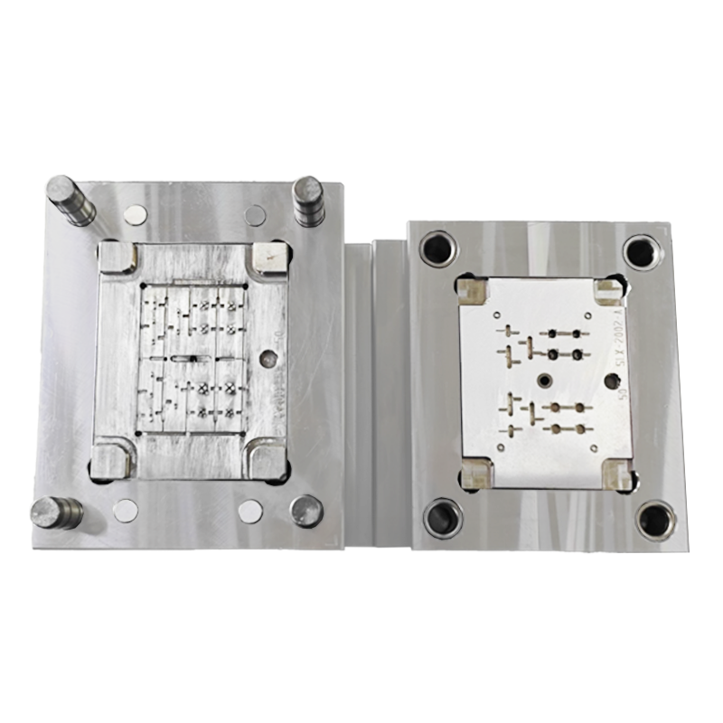
- Cavity: The hollow space in the mold that the molten plastic fills. The cavity is the exact negative of the desired part—including details like holes, ribs, and textures.
- Core: A protrusion in the mold that creates internal holes or recesses in the part (e.g., the hole in a plastic cup).
- Runner System: A network of channels that delivers molten plastic from the nozzle to the cavity. Runners can be “cold” (solidify with the part, requiring trimming) or “hot” (kept molten by heaters, reducing waste).
- Gates: Small openings in the runner system that control the flow of plastic into the cavity. The size and location of gates affect part quality—poorly placed gates can cause defects like weld lines or sink marks.
- Cooling Channels: Passages in the mold that circulate water or oil to cool the molten plastic. Proper cooling is critical to preventing warpage and ensuring the part retains its shape.
- Ventilation Holes: Tiny holes (0.001–0.002 inches) that allow air to escape from the cavity during injection. Without vents, air can become trapped, causing bubbles or incomplete filling.
2.3.3 The Material Handling System
- Dryers: Many thermoplastics (e.g., ABS, PET) absorb moisture from the air, which can cause bubbles or defects in the finished part. Dryers (desiccant or hot-air) remove moisture from pellets before they enter the hopper, typically reducing moisture content to 0.02% or lower.
- Loaders: Automated systems that transport pellets from storage bins to the machine’s hopper, eliminating the need for manual handling.
- Color Mixers: Devices that blend raw plastic pellets with colorants or additives (e.g., UV stabilizers, flame retardants) to achieve the desired part color or performance.
2.4 Key Terminology in Injection Molding: A Glossary for Manufacturers
- Cycle Time: The total time required to complete one injection molding cycle (clamping → injection → dwell → cooling → ejection). Cycle times can range from 10 seconds (for small parts like 瓶盖) to several minutes (for large, thick parts like automotive dashboards).
- Tolerance: The allowable variation in part dimensions (e.g., ±0.005 mm). Injection molding can achieve tight tolerances, making it suitable for precision parts like medical devices.
- Shrinkage: The reduction in size that occurs when molten plastic cools and solidifies. Different plastics have different shrinkage rates (e.g., polyethylene shrinks 1.5–3%, while ABS shrinks 0.5–1.5%). Mold designers account for shrinkage by making the cavity slightly larger than the desired part.
- Warpage: A defect where the part bends or twists after ejection, often caused by uneven cooling or incorrect material selection.
- Flash: Excess plastic that seeps out of the mold’s parting line (the gap between the two mold halves). Flash is typically trimmed off post-production but can indicate a problem with clamping force or mold alignment.
- Weld Line: A visible line on the part where two streams of molten plastic meet and do not fully fuse. Weld lines can weaken the part and are often caused by poor gate placement.
- Sink Mark: A depression on the part’s surface, usually caused by insufficient packing pressure or uneven cooling.
- Hot Runner Mold: A mold with a heated runner system that keeps plastic molten in the channels, eliminating the need to trim cold runners. Hot runner molds reduce waste and improve part consistency.
- Cold Runner Mold: A mold with unheated runners that solidify with the part. Cold runner molds are cheaper upfront but generate more waste (runners must be recycled or discarded).
- Micro-Injection Molding: A specialized process for producing parts with dimensions under 1 mm (e.g., micro-connectors, medical sensors). Micro-injection molding requires high precision and specialized machines.
- Overmolding: A process where two different materials are molded together (e.g., a hard plastic handle with a soft rubber grip). Overmolding is often used to improve ergonomics or functionality.
- Insert Molding: A process where a pre-fabricated component (e.g., a metal screw or electronic connector) is placed in the mold before injection. The molten plastic bonds to the insert, creating a single part.
3. How Injection Molding (Moulage par Injection) Works: A Step-by-Step Breakdown
3.1 Step 1: Clamping – Securing the Mold for Precision
Key Details:
- Clamping Force Calculation: The clamping force (measured in tons) required depends on two factors: the projected area of the part (the area of the part as viewed from the injection side) and the injection pressure (typically 10,000–30,000 psi). The formula for clamping force is:
- Clamping Speed: The mold is closed at a controlled speed—fast enough to minimize cycle time but slow enough to avoid damaging the mold or any inserts (e.g., metal components in insert molding). Modern machines use servo-electric or hydraulic systems to adjust clamping speed with precision.
- Mold Alignment: The mold halves must be perfectly aligned to prevent flash (excess plastic seeping out of the parting line). Machines use guide pins and bushings to ensure alignment, and operators perform regular checks to detect wear or misalignment.
3.2 Step 2: Injection – Melting and Delivering Thermoplastic Resin
Key Details:
- Resin Melting: Plastic pellets are fed from the hopper into the heated barrel. The barrel’s temperature is set based on the plastic type—for example, polyethylene (PE) melts at 160–270°C (320–518°F), while polycarbonate (PC) melts at 220–320°C (428–608°F). The rotating screw inside the barrel mixes the pellets and applies shear heat, ensuring uniform melting.
- Screw Movement: The screw has three zones:
-
- Feed Zone: Near the hopper, where pellets are conveyed forward and preheated.
-
- Compression Zone: Where pellets are melted and compressed, with the screw’s flight depth decreasing to build pressure.
-
- Metering Zone: Near the nozzle, where molten plastic is held at a consistent temperature and pressure before injection.
- Injection Speed and Pressure: Injection speed (measured in mm/s or in/s) determines how quickly the cavity is filled. Fast speeds can reduce cycle time but may cause turbulence (leading to air bubbles), while slow speeds can cause premature solidification (leading to incomplete filling). Injection pressure is the force applied to the screw to push the plastic into the cavity—higher pressure ensures full filling but can increase stress in the part.
- Gate Filling: The molten plastic flows through the runner system and enters the cavity through the gate. The gate’s size and location are critical: a small gate controls flow but may cause shear heating (damaging the plastic), while a large gate can lead to sink marks.
3.3 Step 3: Dwell (Packing) – Ensuring Full Cavity Filling and Reducing Shrinkage
Key Details:
- Packing Pressure: A lower pressure than injection pressure is applied to the screw, ensuring that the cavity remains full as the plastic starts to solidify. Without packing, the plastic would shrink away from the mold walls, creating voids or sink marks.
- Packing Time: The dwell time is typically 1–5 seconds, depending on the part’s thickness. Thicker parts require longer packing times to ensure the center of the part is fully filled before cooling.
- Screw Hold: The screw remains in a forward position during dwell, maintaining pressure on the molten plastic. Once the gate solidifies (preventing more plastic from entering the cavity), the dwell step ends.
3.4 Step 4: Cooling – Solidifying the Part Without Warpage
Key Details:
- Cooling System: Most molds use water cooling—channels drilled into the mold halves circulate cold water (typically 15–25°C / 59–77°F) to absorb heat from the molten plastic. For high-temperature plastics (e.g., PEEK), oil cooling may be used, as oil can withstand higher temperatures without boiling.
- Cooling Time Calculation: Cooling time is the longest part of the injection molding cycle, accounting for 50–80% of total cycle time. It is calculated based on the part’s maximum wall thickness and the plastic’s thermal properties. The formula for approximate cooling time is:
- Uniform Cooling: Uneven cooling is a major cause of warpage. For example, if one side of the part cools faster than the other, the part will bend toward the cooler side. Mold designers ensure cooling channels are evenly spaced and close to the cavity walls to promote uniform cooling.
- Part Temperature at Ejection: The part must be cooled to below its glass transition temperature (Tg)—the temperature at which the plastic becomes rigid—before ejection. If ejected too early, the part may deform; if cooled too long, cycle time increases unnecessarily.
3.5 Step 5: Ejection – Removing the Finished Part Safely
Key Details:
- Mold Opening: The clamping unit retracts the moving platen, opening the mold halves. The opening speed is controlled to avoid damaging the part or the mold—fast enough to reduce cycle time but slow enough to prevent the part from sticking to the mold.
- Ejection Mechanisms: There are several types of ejection systems, depending on the part’s shape and complexity:
-
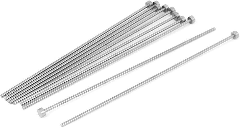
- Ejector Pins: Small, cylindrical pins that push against the part’s surface. Pins are the most common ejection method but can leave small marks on the part (so they are placed on non-visible surfaces).
-
- Ejector Plates: Large plates that push the entire part out of the cavity, ideal for parts with large surface areas.
-
- Air Ejection: Compressed air is blown into the cavity to release the part, suitable for small or delicate parts that could be damaged by pins.
-
- ** Stripper Rings**: A ring that slides over the core to pull the part off, used for parts with internal holes (e.g., cups).
- Part Removal: After ejection, the part may be picked up by a robot (in automated systems) or manually (in small-scale operations). The part is then sent to post-processing (e.g., trimming runners, deburring) or quality control.
- Mold Closing: Once the part is removed, the mold closes again, and the cycle repeats.
3.6 Cycle Time Optimization: Balancing Speed and Quality
Key Strategies for Cycle Time Optimization:
- Reduce Cooling Time: This is the most impactful way to shorten cycle time. Strategies include:
-
- Using a plastic with higher thermal conductivity (e.g., PE instead of PC) to speed up heat transfer.
-
- Optimizing cooling channel design (e.g., adding more channels, moving channels closer to the cavity).
-
- Using conformal cooling—3D-printed cooling channels that follow the cavity’s shape, providing more uniform cooling than traditional drilled channels.
- Optimize Injection Speed: Increasing injection speed can reduce the time to fill the cavity, but only if it does not introduce defects. Using simulation software to predict flow patterns helps identify the optimal speed.
- Minimize Dwell Time: Reducing dwell time to the minimum needed to prevent shrinkage. Over-packing (too much dwell time) increases cycle time and can cause part stress.
- Automate Ejection and Part Handling: Using robots to remove parts and load inserts (in insert molding) eliminates manual labor time and speeds up the cycle.
4. The Unrivaled Advantages of Injection Molding for Mass Production
4.1 Cost Efficiency in High-Volume Production
Why This Happens:
- Economies of Scale: The fixed costs (mold design, machine setup) are spread across thousands of parts. For example, a \(50,000 mold for a plastic part would cost \)5 per unit for 10,000 parts, but only $0.50 per unit for 100,000 parts.
- Low Labor Costs: Modern injection molding machines are fully automated, requiring minimal human intervention. A single operator can monitor multiple machines, reducing labor costs per unit.
- Reduced Waste: With hot runner systems and optimized process parameters, injection molding generates less waste than other processes (e.g., thermoforming, which trims excess material). Scrap plastic can also be recycled and reprocessed, further lowering material costs.
Real-World Example:
- Injection Molding: \(50,000 mold cost + \)0.10 per unit material/labor = Total cost of \(150,000 (\)0.15 per unit).
- 3D Printing: \(0.50 per unit (no upfront cost) = Total cost of \)500,000 ($0.50 per unit).
4.2 Unmatched Precision and Consistency Across Thousands of Parts
How This Is Achieved:
- Tight Tolerances: Injection molding can achieve tolerances as tight as ±0.005 mm (0.0002 inches)—far tighter than processes like 3D printing (±0.1 mm) or thermoforming (±0.5 mm). This precision is critical for parts that need to fit together (e.g., automotive components, electronic connectors).
- Repeatable Process: Computer-controlled machines ensure that every cycle is identical—same temperature, pressure, and speed. This eliminates human error and ensures that each part is a perfect copy of the last.
- High-Quality Molds: Steel molds are machined to exact specifications using CNC technology, ensuring that the cavity shape is consistent across thousands of cycles. High-strength steel molds also resist wear, maintaining precision even after 1 million+ parts.
Real-World Example:
4.3 Exceptional Design Flexibility: From Simple to Hyper-Complex Geometries
What’s Possible:
- Complex Geometries: Parts with undercuts (recesses that require the mold to “split” to eject), ribs (for strength), and thin walls (as thin as 0.2 mm) can be produced with injection molding. For example, a smartphone housing has multiple undercuts for buttons and ports, thin walls to reduce weight, and intricate textures—all made in one cycle.
- Integrated Features: Multiple components can be combined into a single part, reducing assembly time and cost. For example, a plastic chair armrest can be molded with built-in cup holders and USB ports—eliminating the need to assemble separate parts.
- Surface Finishes: Molds can be textured or polished to create a range of surface finishes, from matte to high-gloss. Special effects like chrome plating or soft-touch coatings can also be applied during or after molding.
Real-World Example:
4.4 Broad Material Compatibility: Working with Every Major Thermoplastic
Common Materials Used in Injection Molding:
|
Material
|
Key Properties
|
Typical Applications
|
|
Polyethylene (PE)
|
Low cost, flexible, chemical resistant
|
Plastic bags, bottles, toys
|
|
Polypropylene (PP)
|
High strength, heat resistant, lightweight
|
Food containers, automotive bumpers, medical syringes
|
|
ABS
|
Impact resistant, rigid, easy to paint
|
Electronic housings, toy bricks, automotive trim
|
|
Polycarbonate (PC)
|
High impact strength, transparent, heat resistant
|
Safety glasses, smartphone screens, medical devices
|
|
Nylon (PA)
|
High strength, wear resistant, oil resistant
|
Gears, bearings, automotive parts
|
|
PEEK
|
High temperature resistance, biocompatible
|
Aerospace components, medical implants
|
Material Customization:
- Filled Resins: Resins mixed with additives like glass fibers (for strength), carbon fibers (for conductivity), or talc (for stiffness). For example, glass-filled nylon is used to make strong, lightweight automotive parts.
- Recycled Resins: Post-consumer or post-industrial recycled plastic, which reduces environmental impact and material costs. Many brands (e.g., Coca-Cola, Unilever) now use recycled resins in injection-molded packaging.
- Alloys: Blends of two or more plastics to combine properties. For example, ABS/PC alloy combines ABS’s impact resistance with PC’s transparency and heat resistance.
4.5 High Production Speed: Meeting Global Demand Scales
How Fast Is Injection Molding?
- Cycle Times: For small parts (e.g., 瓶盖,connectors), cycle times can be as short as 10–15 seconds. For larger parts (e.g., automotive dashboards), cycle times are 30–60 seconds. This means a single machine can produce 60–360 small parts per hour, or 60–120 large parts per hour.
- Multi-Cavity Molds: To further increase speed, molds can have multiple cavities—producing 2, 4, 8, or even 32 parts per cycle. For example, a 16-cavity mold for 瓶盖 can produce 16 caps every 10 seconds, or 5,760 caps per hour.
- Continuous Operation: Injection molding machines can run 24/7, 365 days a year—with only minimal downtime for maintenance or mold changes. This continuous operation is critical for meeting large-scale demand.
Real-World Example:
4.6 Reduced Waste: Minimizing Material Loss in Manufacturing
How Injection Molding Reduces Waste:
- Hot Runner Systems: Traditional cold runner molds generate waste in the form of solidified runners (the channels that deliver plastic to the cavity). Hot runner systems keep the runner plastic molten, eliminating this waste. Hot runners can reduce material waste by 20–50%, depending on the part size.
- Precise Shot Control: Injection molding machines use precise shot volume control to ensure that only the exact amount of plastic needed to fill the cavity is used. This minimizes overfilling and scrap.
- Scrap Recycling: Any scrap plastic (e.g., cold runners, defective parts) can be ground up, melted, and reprocessed into new pellets. Most injection molding facilities have on-site recycling systems, closing the loop on material use.
- Lean Design: Mold designers optimize part geometry to use less material without sacrificing strength. For example, adding ribs to a part’s interior increases strength while reducing wall thickness—using 10–20% less plastic.
Real-World Example:
4.7 Post-Processing Versatility: Preparing Parts for End-Use
Common Post-Processing Techniques for Injection-Molded Parts:
- Trimming: Removing excess material like cold runners or flash using automated trimmers or lasers.
- Deburring: Smoothing rough edges or sharp corners using tumblers, sandblasting, or ultrasonic cleaning.
- Painting and Coating: Applying paint, ink, or specialized coatings (e.g., soft-touch, anti-microbial) to improve aesthetics or functionality.
- Plating: Adding a metal layer (e.g., chrome, nickel) to the part’s surface for a decorative or functional finish (e.g., conductivity, corrosion resistance).
- Assembly: Joining multiple injection-molded parts using methods like ultrasonic welding, adhesives, or screws.
- Marking: Adding logos, text, or barcodes using laser engraving, pad printing, or in-mold labeling (IML)—where a label is placed in the mold before injection, bonding it to the part.
Real-World Example:
- Trimming to remove cold runners.
- Deburring to smooth edges.
- Laser engraving to add the brand logo.
- Anti-fingerprint coating to improve grip and appearance.
5. Injection Molding vs. Other Manufacturing Processes: A Comparative Analysis
5.1 Injection Molding vs. 3D Printing: Speed, Cost, and Scale
|
Factor
|
Injection Molding
|
3D Printing
|
|
Production Speed
|
Very fast for high volumes: Cycle times as short as 10 seconds per part; multi-cavity molds produce 1000+ parts/hour.
|
Slow: Even fast 3D printers (e.g., FDM, SLA) produce 1–10 parts/hour for small parts.
|
|
Cost per Unit
|
Low at scale: \(0.05–\)5 per unit for 10,000+ parts (fixed mold costs spread across volume).
|
High: \(0.50–\)50 per unit (no fixed costs, but slow speed and material waste drive up costs).
|
|
Part Quality
|
High: Tight tolerances (±0.005 mm), smooth surfaces, and consistent mechanical properties.
|
Variable: Tolerances (±0.1–0.5 mm), layer lines (visible on parts), and lower strength (due to layer bonding).
|
|
Material Compatibility
|
Broad: Works with all thermoplastics, plus filled resins and alloys.
|
Limited: Most 3D printers use specialized filaments (e.g., PLA, ABS) or resins—few can handle high-performance materials like PEEK.
|
|
Volume Suitability
|
Ideal for high volumes (10,000+ parts).
|
Ideal for low volumes (1–100 parts) or prototyping.
|
|
Design Flexibility
|
High for repeatable complex parts (undercuts, ribs) but requires mold design.
|
Very high for one-off custom parts (no mold needed) but limited by printer capabilities (e.g., no large parts).
|
5.2 Injection Molding vs. Blow Molding: Ideal Applications and Limitations
|
Factor
|
Injection Molding
|
Blow Molding
|
|
Part Geometry
|
Designed for solid or semi-solid parts (e.g., housings, gears) with complex features.
|
Designed for hollow parts (e.g., bottles, tanks) with simple external shapes.
|
|
Wall Thickness Control
|
Excellent: Uniform wall thickness (±5%) via mold design and packing pressure.
|
Poor: Wall thickness varies (±10–20%)—thicker at the bottom, thinner at the top.
|
|
Production Speed
|
Fast for small parts (10–60 seconds/cycle) but slower for large parts.
|
Fast for small hollow parts (e.g., 1000+ bottles/hour) with multi-cavity molds.
|
|
Cost per Unit
|
Low at scale for solid parts; higher for hollow parts (requires more material).
|
Low at scale for hollow parts (uses less material than injection molding for the same volume).
|
|
Material Compatibility
|
Broad: All thermoplastics, plus filled resins.
|
Limited: Primarily uses PE, PP, PET, and PVC (materials with good stretchability).
|
|
Application Suitability
|
Ideal for solid parts (automotive components, electronics) and small hollow parts (e.g., cosmetic jars).
|
Ideal for large hollow parts (e.g., 5-gallon buckets, automotive fuel tanks) and packaging (bottles).
|
5.3 Injection Molding vs. Extrusion: Shaping Continuous vs. Discrete Parts
|
Factor
|
Injection Molding
|
Extrusion
|
|
Part Type
|
Discrete parts (individual components: e.g., gears, housings).
|
Continuous shapes (e.g., pipes, sheets, window frames) cut to length.
|
|
Design Complexity
|
High: Can produce parts with undercuts, ribs, and intricate details.
|
Low: Limited to simple, continuous cross-sections (no undercuts or complex features).
|
|
Tolerance Control
|
Excellent (±0.005 mm) for discrete parts.
|
Good (±0.1–0.5 mm) for continuous shapes but varies along the length.
|
|
Production Speed
|
Fast for discrete parts (1000+ parts/hour with multi-cavity molds).
|
Very fast for continuous shapes (e.g., 100+ meters of pipe/hour).
|
|
Cost Structure
|
High upfront mold costs; low per-unit costs at scale.
|
Low upfront die costs; low per-unit costs for continuous production.
|
|
Application Suitability
|
Ideal for mass-producing discrete parts with complex geometries.
|
Ideal for producing large volumes of continuous shapes (pipes, sheets, profiles).
|
5.4 Injection Molding vs. Compression Molding: Efficiency for Complex vs. Simple Designs
|
Factor
|
Injection Molding
|
Compression Molding
|
|
Material Type
|
Primarily thermoplastics (can be melted and reshaped).
|
Primarily thermosets (e.g., epoxy, phenolic) but also thermoplastics.
|
|
Cycle Time
|
Fast (10–60 seconds/cycle) for thermoplastics.
|
Slow (1–5 minutes/cycle) for thermosets (requires curing time).
|
|
Design Complexity
|
High: Can produce parts with undercuts, holes, and intricate details.
|
Low: Limited to simple shapes (no undercuts) due to mold opening constraints.
|
|
Part Size
|
Small to large (grams to kilograms) but limited by machine clamping force.
|
Large parts (e.g., automotive bumpers, composite panels) due to low pressure requirements.
|
|
Waste
|
Low (5–10%) with hot runners; scrap can be recycled.
|
High (10–20%) due to excess material (flash) that must be trimmed.
|
|
Application Suitability
|
Ideal for complex thermoplastic parts (electronics, medical devices).
|
Ideal for large thermoset parts (e.g., circuit breakers, automotive gaskets) or composite materials.
|
5.5 Injection Molding vs. Thermoforming: Cost and Precision for Thin-Walled Parts
|
Factor
|
Injection Molding
|
Thermoforming
|
|
Wall Thickness
|
Uniform (±5%) even for thick parts (up to 50 mm).
|
Uneven (±10–30%)—thinner in stretched areas; limited to thin walls (0.2–3 mm).
|
|
Part Complexity
|
High: Can produce parts with undercuts, ribs, and internal features.
|
Low: Limited to simple shapes (no undercuts) due to sheet stretching constraints.
|
|
Production Speed
|
Fast (1000+ parts/hour with multi-cavity molds) for small parts.
|
Slow (100–500 parts/hour) due to sheet heating and cooling time.
|
|
Cost Structure
|
High upfront mold costs (\(10,000–\)1M+); low per-unit costs at scale.
|
Low upfront tool costs (\(1,000–\)10,000); higher per-unit costs (due to waste).
|
|
Material Waste
|
Low (5–10%) with hot runners.
|
High (20–50%)—excess sheet material is trimmed and often cannot be recycled.
|
|
Application Suitability
|
Ideal for thin-walled parts with precision (e.g., medical trays, electronic housings).
|
Ideal for low-volume thin-walled parts (e.g., custom packaging, display trays).
|
Final Comparative Verdict
6. Key Industries Dependent on Injection Molding (Moulage par Injection)
6.1 Automotive Industry: Powering the Production of Critical Components
Key Applications:
- Interior Components: Dashboard panels, door handles, seat frames, cup holders, and air vents. These parts require complex geometries (e.g., integrated air ducts in dashboards) and consistent aesthetics—both of which injection molding delivers. For example, a Tesla Model 3’s dashboard is a single injection-molded part with integrated touchscreen housing and air vents, reducing assembly time and weight.
- Exterior Components: Bumpers, mirror housings, grille inserts, and lighting bezels. These parts need to withstand harsh weather (UV radiation, temperature changes) and impacts—so they are made from durable materials like ABS/PC alloy or glass-filled PP via injection molding.
- Under-the-Hood Components: Sensor housings, battery casings (for electric vehicles), and fluid reservoirs. These parts require high heat resistance and chemical compatibility—materials like PPS (polyphenylene sulfide) or PA (nylon) are used, with injection molding ensuring precise fits for sensors and wiring.
- Electrical Components: Connector housings, wire harnesses, and EV charging port components. These parts need tight tolerances to ensure electrical conductivity and safety— injection molding achieves tolerances of ±0.01 mm, preventing short circuits.
Why Injection Molding Is Critical:
- Weight Reduction: Injection molding allows the use of lightweight plastics instead of metal, improving fuel efficiency (for internal combustion engines) and range (for EVs). For example, replacing a steel bumper with an injection-molded plastic bumper reduces weight by 30–50%.
- Cost Efficiency: With millions of vehicles produced annually, injection molding’s low per-unit costs are essential. A single mold for a door handle can produce 1 million+ parts, reducing cost per unit to under $1.
- Durability: Injection-molded automotive parts can withstand 10+ years of use, withstanding temperature extremes (-40°C to 120°C / -40°F to 248°F) and mechanical
-

Dongguan Sanlixin Plastic Technology Co.,Ltd
Shenzhen Sanlixin Technology Co., Ltd. and Dongguan Sanlixin Plastic Technology Co., Ltd. is a manufacturer integrating precision plastic mold design, mold opening, single (double) color injection molding, IML injection molding processing, producing various single (double) color, IML process high-end appearance decorative structural parts, two-color buttons, USB dust plugs, panels and other plastic products, providing customers with fast, excellent, Midea all-round service, the company has 15 years of experience in precision plastic mold design, processing and production, with a variety of advanced machine injection molding equipment with excellent quality and fast service to win the trust and strong support of our customers.
Understanding Injection Molding Tolerances: Key Factors & Best Practices
OEM or ODM? How Should Enterprises Choose the Right OEM/ODM Model?